K Factor in SOLIDWORKS
The K factor represents a constant that relates to bending or forming of materials, such as in sheet metal work. It is a value that determines the distribution of stress during bending and is used in the calculation of the amount of material required to form a specific bend in Sheet Metal.
Understanding K Factor:
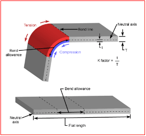
- The K factor is used to determine the location of the neutral axis of a material when it is being bent.
- When a sheet metal component is bent, the material on the outer side of the bend is stretched, while the material on the inside of the bend is compressed.
- The neutral axis is the plane within the material where neither tension nor compression occurs during bending.
- The K factor helps identify how much material will be stretched and how much will be compressed during the bend.
Typically, the K factor ranges from 0.3 to 0.5, but it can vary depending on the material type, thickness, and bending process.
Influence on Bending:
A higher K factor implies that a greater proportion of the material’s thickness is involved in the stretched (or
Example in Practice:
When designing a part with sheet metal, you might calculate the necessary length of material to ensure that after bending, the final part fits within specified dimensions. By applying the K factor, you can more accurately predict how the material will behave during bending and how much to account for in terms of stretch and compression.
The K factor is crucial for determining the bend allowance, which is the amount of material required to make a bend. It helps engineers figure out the required length of material before bending, ensuring the part fits the intended dimensions after forming.
By using the K factor, engineers can calculate the flat length of a piece of sheet metal by considering the radius of the bend, material thickness, and bend angle. This is especially important when designing parts that need to be cut from a flat sheet before bending.
Bend Allowance Calculation
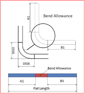
In the fabrication of a bracket, if you know the thickness of the material, bend radius, and the bend angle, you can calculate the bend allowance using the K factor, ensuring you don’t over- or underestimate the amount of material needed.
Bend Deduction Calculation
The K factor also helps calculate the bend deduction, which accounts for the material “lost” or compressed during the bending process. This is very critical for accurate design, as it ensures parts are fabricated to the correct sizes despite the material being distorted during the bending process.
Once the bend allowance is calculated, the bend deduction helps determine how much shorter the final part will be due to compression on the inside of the bend. This helps in adjusting the cut length of the flat material before bending. Without this adjustment, the final part might not fit properly.
Predicting Material Behavior During Bending
The K factor allows engineers to predict how different materials will behave during bending, taking into account variations in material properties like elasticity, ductility, and thickness.
Different materials require different K factors because they have different physical properties. For instance, a softer material like aluminum may have a different K factor compared to a harder material like steel.
In the aerospace industry, engineers use the K factor to understand how various materials (aluminum, titanium, etc.) will behave when bent to ensure the correct amount of stretch and compression, which affects the structural integrity of the part.
Minimizing Material Waste
By calculating the correct bend allowance and bend deduction using the K factor, manufacturers can optimize material usage, reducing waste.
By accurately predicting how much material will be required for a part and adjusting for the bend’s effects, manufacturers can minimize scrap and ensure that the maximum amount of usable material is efficiently utilized.
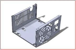
Example: In mass production, such as making metal enclosures for electronic devices, the K factor helps in determining the most efficient way to cut and bend the metal sheets, reducing waste and lowering material costs.
Design for Manufacturability
The K factor is part of the design-for-manufacturability (DFM) process, which ensures that parts are designed in a way that makes them easy and cost-effective to manufacture.
Understanding the K factor allows engineers to design parts with the appropriate bend radii and material thickness to reduce the chance of defects or failures in production. This also helps in choosing the best material for the job.
When designing a consumer appliance housing, engineers would use the K factor to ensure the bends are not too tight (which could cause cracking) and that the material thickness is optimal for both strength and ease of manufacture.
Optimization of Sheet Metal Cutting and Bending
When working with complex parts requiring multiple bends, the K factor helps to optimize the cutting and bending processes, ensuring the final product meets precise dimensions and tolerances.
The K factor assists in determining the proper sequence of bends and cuts to avoid excessive stretching or compression that could affect the part’s final shape.
In automotive manufacturing, the K factor is used to optimize the sheet metal parts (e.g., body panels, brackets) to ensure each part fits accurately without excess material or warping during the production process.
Understanding the K Factor in SOLIDWORKS
K Factor in SOLIDWORKS is a ratio that relates the neutral axis (the point of no deformation during bending) to the material thickness.
The value of the K factor helps define how much of the material’s thickness is stretched or compressed during the bend.
It is important for calculating bend allowance and bend deduction, which in turn are used to determine the flat pattern (the initial cut before bending).
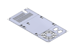
Create a Sheet Metal Part: In SOLIDWORKS, you can create a sheet metal part by using the Sheet Metal tool. This tool allows you to define a part with features such as bends, flanges, and cuts.
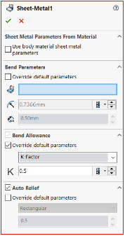
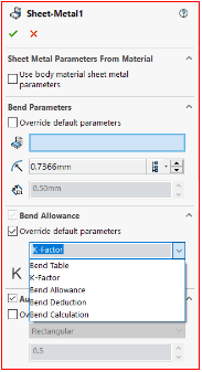
Set the K Factor: When defining the material for the sheet metal part, SOLIDWORKS allows you to specify the K factor in the Sheet Metal Parameters. Here’s how you can set it
Open the Sheet Metal feature in SOLIDWORKS.
Right-click the Sheet Metal feature in the Feature Manager, and select Edit Sheet Metal.
In the Sheet Metal properties, there is an option to input the K factor under the Bend Parameters section.
Enter the appropriate K factor value for the material (this can be found from material-specific references or by experimentation).
Calculating Bend Allowance and Bend Deduction
Bend Allowance: The K factor is used to calculate the bend allowance, which represents the length of material that is used for each bend. This ensures the material can be cut accurately before bending.
Bend Deduction: The K factor is also used to calculate the bend deduction, which accounts for how much material is lost or compressed during the bending process.
SOLIDWORKS automatically calculates the bend allowance and bend deduction for you once the K factor is set. This helps in generating a flat pattern that can be sent for manufacturing, ensuring that the part’s final size is accurate.
Flat Pattern Generation
When designing sheet metal parts, the flat pattern is the 2D representation of the part before it is bent. The flat pattern is essential for cutting and manufacturing the part. The K factor is used to unfold the part accurately, allowing SOLIDWORKS to calculate:
The true flat length of each side. The required cuts to achieve the desired bends.
Once the sheet metal part is created, go to the Flatten feature (Sheet Metal tab).
SOLIDWORKS automatically applies the K factor to unfold the sheet metal part into a flat layout, considering the bend radii and material thickness.
Adjusting K Factor for Different Materials
Different materials have different stretching and compression characteristics, which affect the K factor. SOLIDWORKS allows you to adjust the K factor depending on the material being used (e.g., aluminum, steel, copper, etc.). This is useful because softer materials will require a different K factor than harder materials.
To adjust for different materials: In the Material tab, choose the material you are working with. The K factor value can either be selected from predefined options or manually entered, depending on the material and design specifications.
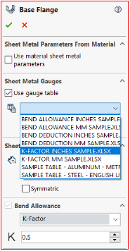
Customizing K Factor in a Sheet Metal Gauge Table
SOLIDWORKS allows you to create custom gauge tables for different material thicknesses and corresponding K factors. This table can be customized for specific projects or materials. You can use gauge tables to set up multiple material types and thicknesses, and each material thickness can have its own K factor based on industry standards or material testing.
Impact of K Factor on Design
Setting the correct K factor ensures that the final part dimensions after bending are accurate. If the K factor is not correctly set, the part may not fit together as expected.
By accurately calculating the flat pattern length and considering the K factor, SOLIDWORKS can help minimize material waste by providing accurate cut lengths.
When designing tooling or creating specific bend radii, knowing the K factor helps ensure that the bending process will not cause defects such as material cracks, wrinkles, or other problems.
Conclusion: If you’re working with a new material or a specific manufacturing process, you may need to experiment with the K factor to find the best value for that scenario. Use standard K factor values as a baseline and adjust as needed. Many materials have common K factor values
In sheet metal fabrication and other bending processes, the K factor is a crucial parameter that helps engineers design parts efficiently by accounting for how a material will stretch or compress during the bending process.
Proper application of the K factor leads to more accurate cuts and less material waste.
Contact Us: Have questions or need assistance? Feel free to reach out!
Email: mktg@egs.co.in
Phone: +91 94454 24704