The response spectrum method is used to compute inertial response, estimates of response quantities developed for each mode, each direction of excitation and each input, if multiple inputs are considered. The total response is then formed by summing over all modal component, spatial component and excitation component responses. It estimates the structural response to short, nondeterministic, transient dynamic events. Examples of such events are earthquakes and shocks. Since the exact time history of the load is not known, it is difficult to perform a time-dependent analysis.
It is a widely used procedure for performing elastic dynamic seismic analysis, representing the set of the maximum acceleration, velocity, or displacement responses of a family of single-degree-of-freedom (SDOF) damped oscillators.

Fig: 1
For a given time period of the system, the maximum response is picked. This process is continued for all ranges of possible time periods of the SDOF system. The final plot with the system time period on the x-axis and response quantity on the y-axis is the required response spectra pertaining to specified damping ratio and input ground motion as acceleration, velocity, or displacement response.
Factor Influencing Response Spectra:
- Damping in the system
- Time period of the system
- Energy release mechanism
Errors in Evaluation of Response Spectrum:
Truncation Error: In general, a truncation error exists in numerical methods for integrating differential equations.
Rounding the Time Record: For earthquake records digitized at irregular time intervals, the integration technique proposed in this report requires rounding of the time record, and the attendant error depends on how the rounding is done. For round-off to 0.005 sec, the average error in spectrum values is expected.
Error Due to Discretization: In any numerical method of computing the spectra, the response is obtained at a set of discrete points. Since spectral values represent maximum values of response parameters which may not occur at these discrete points, discretization introduces an error which gives spectrum values lower than the true values. Multi-degree of freedom (MDOF) systems are usually analyzed using Modal Analysis. A typical MDOF system with ‘n’ degrees of freedom undergoes deformations in several possible ways. These deformed shapes are known as modes of vibration or mode shapes.
In SolidWorks Simulation, we can predict the displacement, maximum stress induced, and frequency with respective mode shapes of the system, with response as acceleration, velocity, or displacement input to the system. Irrespective of the system type, the system can be regular or irregular, as shown in Fig: 2 & Fig: 3.
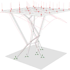
Fig:2(irregular Structure)

Fig:3(Regular)
Regular Structure:
The design shall be approximately symmetrical in plan with respect to two orthogonal axes with the following assumptions:
- Location of joints with equal spacing in the design.
- No horizontal or vertical irregularity of the structure.
- No change in material or shape of the structure cross-section.
Irregular Structure:
If the design does not follow any assumptions of the regular system, it becomes an irregular structure. Most of the mechanical designs are irregular in nature, as there may be material changes to the main members to improve the strength of the design.
There are different methods that are used for combining the response of each direction of the system. The methods for MDOF systems are as follows:
- Square root of sum of squares (SRSS) Method
- Absolute Sum (ABSSUM) Method
- Complete quadratic combination (CQC) Method
- Naval Research Laboratory (NRL)
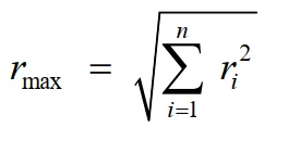
Square Root of Sum of Squares (SRSS) Method:
The maximum response is obtained by the square root of the sum of the squares of the response in each mode of vibration. The effect is calculated for each individual frequency of the system with the defined response at different directions. These responses are summed up and averaged.
Limitation of SRSS:
- There is a poor estimator of peak responses when applied to systems with closely spaced natural periods.
- Significant errors are caused when working with irregular systems.
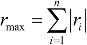
Absolute Sum Method:
The peak responses of all the modes are added algebraically, assuming that all modal peaks occur at the same time. The maximum response is given by:
Complete Quadratic Combination (CQC) Method:
The previously illustrated errors inherent in the absolute sum or the SRSS method are rectified with CQC. The maximum response from all the modes is calculated as:
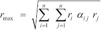
- rmax is the maximum response
- ri, rj are the maximum responses in the ith and jth modes
- αij is the Cross Modal Coefficient
- ξ is Modal Damping Ratio
- β is Frequency Ratio [ ]
Naval Research Laboratory (NRL) Method:
The Naval Research Laboratory (NRL) method is used to combine the peak responses from all mode shapes into overall displacements and stresses. It is a modification of the SRSS Method, taking the absolute value of the response for the mode that exhibits the largest response and adding it to the SRSS response of the remaining modes. The maximum response from all the modes is calculated as:
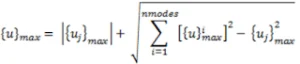
Where {uj}max represents the mode with the largest response among all modal responses.
All the above methods discussed are available in SolidWorks Simulation. According to the structure type and the user requirement, we can define the mode combination method, as shown in Fig: 4.
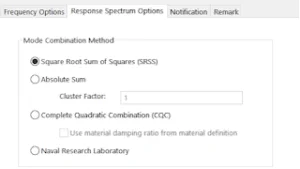
Fig: 4
We have discussed the different mode combination techniques in Response Spectrum by SOLIDWORKS Simulation, the purpose of the different techniques, and also the model equations of the techniques with their limitations.