Boosting the performance in gearbox requires a novel gear tooth profile, parametric optimization, proper alignment, allowable backlash, etc. The industries necessitate a unique approach to gear design with high quality, high strength-to-weight ratio material, longer fatigue life, and high load-carrying capacity. Research and development play a critical role in industrial gears at each stage, starting from gear design with proper material selections and improving the service life of the gearbox.
Finite Element Analysis allows the complete gearbox components to be modeled and evaluated virtually before it is fabricated and put into the real work environment. In recent years, High Power Transmission Gearbox Design has been developing in the direction of high torque, high speed with less noise, vibration reduction, and compact in size. During high-speed running conditions, the gearbox experiences higher contact and bending stress, which leads to pitting and tooth breakage, respectively.
Therefore, FEA is used to determine the contact and bending strength of the gear drives to ensure the efficiency of the industrial gearbox with high load-carrying capacity. In addition, the estimation of time-varying mesh stiffness and transmission error to study the dynamic characteristics of gear drives under high power transmission. The methodology for estimating the stress and fatigue life through FEA is shown in Figure 1.
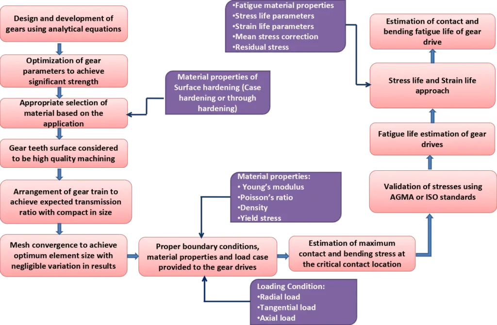
Figure 1: Methodology for fatigue life estimation of gear drives
Failure modes on industrial gear
Failure modes on industrial gears are classified as surface pitting failure, tooth breakage fatigue failure, scuffing, wear, plastic deformation, and corrosion. Fatigue failure in gear drive is predominant, which causes crucial damage to the complete mechanical system. Also, under high-speed operation, the gear tooth experiences higher contact and root stress at the critical region, dependent on temperature and misalignment.
The maximum contact stress at the critical contact tooth surface leads to contact fatigue failure, which results in pitting and scuffing. Pitting leads to macro crack initiation, and it propagates to cavities on the tooth surface. Scuffing failure is caused due to adhesive wear between two contact surfaces, which creates spot welding and tearing. In addition, the fatigue wear caused due to the effect of asperities between the contact teeth regions will induce high plastic deformation.
One of the solutions for increasing the contact fatigue life is to decrease the limiting circle radius at the drive side, which increases the radius of curvature at the single and double tooth contact region for normal contact ratio gears. FEA is used to determine the contact fatigue crack initiation life to predict the service life of gear drives. The maximum bending stress at the critical root of the gear tooth profile leads to crack initiation, and it propagates to tooth breakage.
The numerical analysis shall be carried out to estimate the stress intensity factor (SIF) at the critical root crack along the face width of the gear tooth profile. For increasing the bending fatigue life, the trochoidal profile shall be provided at the root to avoid interference with higher root strength. The trochoidal profile needs to meet the involute profile at the point of tangency, and that intersection point is the limiting point. Similarly, the service life between the crack initiation and crack propagation is determined at the root of the gear.
Furthermore, the misalignment between the gear and pinion will reduce the effective contact region of tooth contact and increase the contact and bending stress, which also leads to high vibration and noise inside the gearbox. Therefore, the estimation of contact and bending stress with fatigue life provides great significance and is trustworthy for designing a high power transmission gearbox design. The pictorial representation of contact fatigue failure and bending fatigue failure is shown in Figure 2 and 3, respectively.
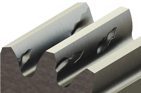
Figure 2: Contact fatigue failure – Macro pitting
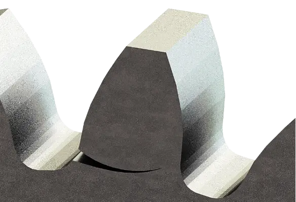
Figure 3: Bending fatigue failure – Tooth breakage
Finite Element Analysis on gearbox
The finite element approach is an effective tool for investigating the contact analysis of gear meshing and optimization. The estimation of maximum contact and bending stress at the critical region of the gear drives is based on linear elastic analysis. Following this, fatigue analysis is carried out to estimate the contact and bending fatigue strength of the gear pair. A schematic representation (Fig.1) of the proposed computational contact and bending fatigue life estimation is separated into different stages.
In the first step, design and development of 3D gear models for step-up or step-down gearbox with space constraint and transmission ratio are conducted. Also, the supporting components such as bearings, gear shafts, seals, bearing covers, etc. shall be included. Figure 4 depicts the 3D Epicyclic gear with compound gear arrangement.
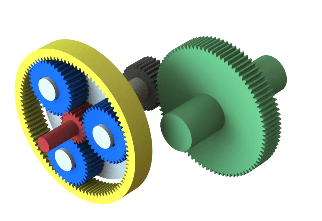
Figure 4: 3D Epicyclic gear with compound gear arrangement
The second step is to provide appropriate material properties and boundary conditions, and load applied on the gear teeth. The force applied on the single tooth contact region is considered as the critical region, which increases the contact and bending stress. Only tangential and radial force will act on the spur gear, which causes bending moments on the shaft. The helical gear will experience tangential, radial, and axial force, which leads to bending in the perpendicular plane.
The applied torque in the gear is equal to the sum of the distributed forces. In gear teeth mating conditions, the applied load will be shared based on contact ratio to single tooth point contact and double tooth point contact for normal contact ratio gears. The third step is to conduct the mesh convergence to attain optimum mesh quality. The FEA estimates the stress distribution along the mesh cycle and is used to determine the maximum contact and bending stress at the critical region.
In the fourth step, fatigue analysis shall be determined based on the combination of stress distribution data and fatigue material properties. The contact and bending fatigue life of the gear drive is estimated using stress and strain life approaches with the effect of mean stress correction, residual stress, and notch factor. This fatigue analysis will predict and ensure the service life of the gear drive. In addition, the optimization of important gear parameters will improve the contact and bending fatigue life of the gear drive in order to achieve a significant transmission ratio.
The gear parameters like module, pressure angle, transmission ratio, addendum modification factor, teeth number, pressure angle, helix angle, face width, etc. can be optimized to achieve higher contact and bending fatigue life. Based on the parametric optimization, the gear design should meet higher efficiency, reliability, load-carrying capacity, and compact in size. The von Mises stress and principal stress at the contact tooth surface and critical root respectively are shown in Figure 5 and 6. Also, the contact and bending fatigue life of spur gear drive is shown in Figure 7 and 8.
Furthermore, the heat generation due to friction is one of the major factors in gear transmission failure. The thermo-mechanical analysis shall be carried out to determine the deformation due to thermal effects, frictional heat flux under high load, and thermal fatigue on gear drives. This thermo-mechanical analysis is important to check the stability and thermal failure on gears and gearbox components.
Also, the computational fluid dynamics analysis is used to study the splashing power loss and oil distribution inside the gearbox. Finally, the FEA results are validated with the analytical calculation based on gear standards or experimentally to check the simulation accuracy.
Summary
The accurate finite element analysis of gear strength in an industrial gearbox is required to ensure efficient performance, longer service life, and increased reliability. To optimize the gearbox design, simulation on stress analysis, fatigue, gearbox lubrication, thermal, acoustic, and vibration shall be carried out under various input speeds, torque, and friction factors. The engineers can choose an ideal gearbox with better performance with the aid of finite element analysis.
The gearbox manufacturers will be able to maintain their competitive advantage in the market owing to this study, which will save costs and turnaround times. The gear type selection, appropriate material selection, gear strength calculations, shaft selection and manual calculations, tolerance analysis and optimization, bearing selection, gearbox housing, centre distance, contact ratio, backlash, operating temperature, lubrication selection, design for life, design for safety, design for quality, and gear design standards must all be taken into account during the entire gearbox design process. 2D manufacturing drawings with GD&T shall be done for complete gearbox assembly with manufacturing tolerances. Finally, the correlation with gearbox prototype testing shall be carried out.