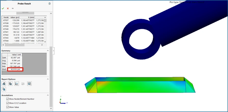
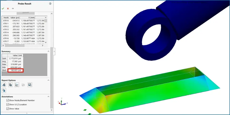
How Can We Numerically Validate a Spreader Beam Using – SOLIDWORKS Simulation?

Numerical Validation of Spreader Beam – SOLIDWORKS SIMULATION

Knowing how to model and validate the spreader beam can actually make us to understand the proper pre-processing, solving and post-processing that is involved in any CAE tool.

SOLIDWORKS SIMULATION
FEA Tools that are going to be involved here are as follows 
  1.  SOLIDWORKS SIMULATION
  2. 3DEXEPREIENCE SIMULIA &
  3.  Abaqus Legacy

We plan to write this Numerical Validation of Spreader Beam as three parts by the usage of CAE Tools. First to begin with the problem represented in the Figure 1, has been solved by the following element selection and its boundary conditions.

Numerically when spreader beam is represented, it can be represented in two ways of element selection i.e., Either by selecting Beam element (1D Element) or selecting Solid elements(3D Element).

In this blog we will be discussing the advantages and disadvantages that we are going to face depending on the selection of elements

Spreader Beam can be analyzed by modelling

  • Entire beam or Symmetrical Beam into 3D CAD model and Validated with Solid Element Beam Model (3D Element)

  • Entire beam into 3D CAD model and Validated with Beam Element (1D Element)

SOLIDWORKS SIMULATION

By default, Sling Rod has been modelled as Linkage Rod as shown in figure 2

Solid Element (3D) Beam Model – Boundary Conditions

  1. Load

  2. Interaction

  3. Constraints

1. Load ( Same for Both Cases)
  • 3000Lbs of weight has to be lifted

  • 3000/2 = 1500Lbs load at a distance of 2.85ft from both end

2. Interaction – Bonded (Same for Both Cases)
  • All interaction is treated as Bonded, since all parts will be welded together

3. Constraints
  • All DoF arrested (Case 1)

  • Free at Y & Z (Case 2), Since Solid Elements (3D Element) have only Translational DoF, Translation along X (At Solid Beam End Faces) should be restrained to achieve bending.

SOLIDWORKS Simulation
  • Beam when Modelled and Validated with Solid Element – Usage of Full Model Approach

  • Solid-type elements, in this case, are tetrahedrons in place of all modeled geometry

  • Computational Cost with respect to time is high

  • Solid Elements, gives good results when beam length is in higher range, but lacks in stress prediction

  • Solid Element – Full Model Approach

            Case 1: All DoF arrested ( X, Y & Z) 
SOLIDWORKS Simulation
  • Solid Element – Full Model Approach

Case 1: All DoF arrested ( X, Y & Z)

Free Body Forces

SOLIDWORKS Simulation

Solid Element – Full Model Approach

Case 2: Free at Y & Z

Free Body Forces

SOLIDWORKS Simulation

Displacement

Spreader Beam

Shear Stress

Allowable shear = 371 Psi

Shear Stress  Allowable Shear

Solid Element – Symmetry Model Approach

Case 1: All DoF arrested ( X, Y & Z)

Free Body Forces

Solid Element – Symmetry Approach

Case 1: All DoF arrested ( X, Y & Z)

Free Body Forces

Displacement

SOLIDWORKS Simulation

Shear Stress

Allowable shear = 371 Psi

Shear Stress  Allowable Shear

Solid Element – Symmetry Approach

Case 2: Free at Y & Z

Free Body Forces

SOLIDWORKS Simulation

Free Body Forces

SOLIDWORKS Simulation

Displacement

SOLIDWORKS Simulation

Shear Stress


Free Body Force

Displacement

Shear Stress

Full Model Approach


Case 1

97.5% Deviation

0.129mm

62.918Psi

Case 2

0 to 1.5% Deviation

0.441mm

182.051Psi

Symmetric Approach


Case 1

98.5% Deviation

0.126mm

49.731Psi

Case 2

0 to 1.2% Deviation

0.585mm

181.25Psi

As stated earlier, we can understand that, the maximum amount of deflection variation has been observed between two approaches. But regarding the stress developed we can see that there is a correlation. And also, by referring many Journals we can understand that the maximum of stress variation is observed when lengthier beam has been used.

As we discussed the calculations for Solid approach here, we will discuss the beam Element approach on upcoming blogs of this CAE Validation Series. Ciao!

Contact Us: Have questions or need assistance? Feel free to reach out!

Email: mktg@egs.co.in
Phone: +91 94454 24704

Leave a Comment

Your email address will not be published. Required fields are marked *

Scroll to Top